I recently bought a Hue Bridge to experiment a bit with Zigbee and 802.15.4. Following two posts for the hardware version 2.0 and some comments about the differences to version 2.1 I was able to get shell access on my 2.1 hardware.
As there is up to now no complete guide I describe here, what I did:
Opening the case is straigth forward. Just remove the two lower nubsis at the bottom and unscrew the two torx screws; then carefully unclip the bottom.
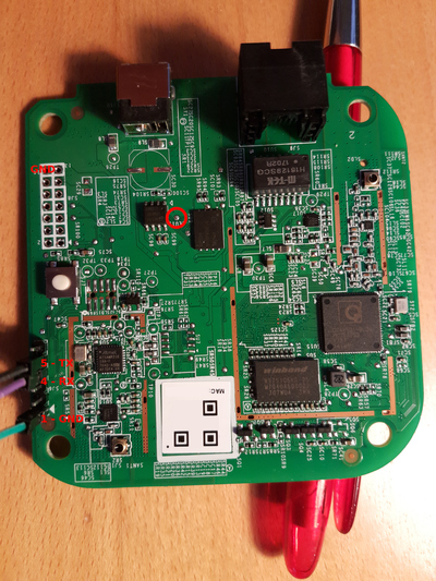
The header on the left side on the image gives access to the UART. Pin 1 is ground, pin 4 is the board's RX (so connect your adapter's TX) and pin 5 is the board's TX. The voltage level is 3.3 V. Note however that the board doesn't boot (after a cold start) with its TX connected so leave that unconnected until after the bootloader is up.
To stop the bootloader short the test point marked with a red cycle on the image near the NAND flash to ground for a few seconds when plugging in the power cord. I used pin 14 of SJ8 (the unassembled header on the left above the factory reset button). This makes the bootloader fail to read the kernel image from NAND and then drop to a shell.
Then after connecting RX you can do there:
setenv bootdelay 3
setenv security '$5$uaS2DwZOsch$2H76tTh0yLzH8LfIkg7z1icoYZLeLGV.Gpo3quhZSe2'
saveenv
reset
After that the machine boots up and you can login with username root and
password lala. (If you want a different password, set security in U-Boot accordingly. I did
mkpasswd -m sha-256
to generate the necessary string.)
After contacting Philips asking for the GPL code running on the bridge I got a code drop and looked a bit around in the source code. Here are some findings:
Having the boards UART TX connected to an USB adapter influences the register
RST_BOOTSTRAP at offset 0x180600b0. This is used to determine how memory is
initialized (in function ath_ddr_initial_config defined in
qsdk/qca/src/qca-legacy-uboot/board/atheros/common/init-953x.c). The naming
of the register together with the board's behaviour suggests that is it sampled
at cold boot only and bit0 then contains the state of the TX pin. So I guess
the machine not (cold) booting with TX connected could be fixed with a hardware
modification removing (or weakening) a pullup on my USB adapter. But I'm more
of a software guy with infinitesimal solder skills, so I will live with
reconnecting TX for each cold boot. Alternatively patching the bootloader to
ignore the RST_BOOTSTRAP might be an option.
I will keep you updated on any progress here.